8 Essential Steps to Perform a Voltage Drop Test
What's your priciest callback from low voltage at the load? Voltage drop is easy to gloss over in precon and expensive to fix after energizing, often tripping controls.
Rework often runs 4-10% of project cost (with studies ranging 1-20%). The fix isn't guesswork. It's a simple, standardized voltage drop test you can run the same way every time. Measure at the source, measure at the load under typical operating conditions, and use the delta to make a clear pass/fail call against project specs.
When results are captured in a structured template, you'll spot trends early and avoid nuisance trips after energization.
What Is a Voltage Drop Test?
A voltage drop test measures voltage at the source and at the load under typical operating conditions. The difference is the loss across conductors, terminations, and devices. You measure at the source, measure at the load, and the delta becomes your pass/fail signal.
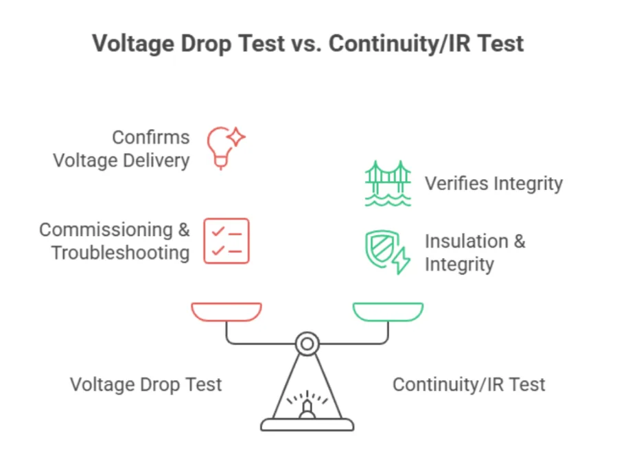
Electrical teams use it during commissioning to validate new installations and during troubleshooting to isolate performance issues. Unlike continuity or insulation resistance tests, which verify integrity and insulation, a voltage drop test confirms that the circuit delivers adequate voltage under load.
Results often end up in document management tools, but the real value comes when readings are structured for pass/fail logic and trend analysis.
Set pass/fail by project specs, owner requirements, and manufacturer guidance. If none exist, use common industry norms:
<= 3%voltage drop on branch circuits<= 5%total (feeder + branch), with a2%feeder target
Document the threshold you're using and test against it so the GC and owner know the line.
What Is the Purpose of a Voltage Drop Test?
Excessive drop shows up as nuisance trips and motor overheating, small issues that turn into warranty headaches. A voltage drop test proves the circuit delivers required voltage under load. Testing early protects your bid assumptions and helps you defend scope.
You can use readings to resize conductors, reroute, or price remediation before problems become callbacks.
Why Voltage Drop Matters for Feeders and Branch Circuits
Feeder drop sets the baseline for everything downstream. HVAC motors lose torque and equipment runs hotter. Branch drop then pushes end loads over the edge, so LED drivers may flicker or shut off.
Undervoltage also hits hardest at startup. Inrush or locked-rotor currents (about 6-8x FLA is typical; confirm nameplate/LRA) amplify drop, causing momentary sags that can stall motors and trip breakers. A voltage drop test verifies both running and start conditions across feeder and branch circuits so systems stay stable under real load.
Common Causes of Excessive Voltage Drop
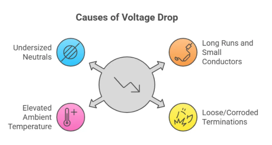
Long Runs and Small Conductors
Assume #12 Cu THHN at about 75 C with DC resistance around 1.93 ohm/1000 ft, single-phase, and power factor near 1; loop length is 2x one-way run. For long feeders or three-phase circuits, use impedance (R + jX) at actual power factor for better accuracy.
Quick reference under those assumptions:
| Voltage | Amperage | Max one-way run (ft) | Approx. voltage drop |
|---|---|---|---|
| 120 V | 15 A | ~60-65 ft | ~3% |
| 120 V | 20 A | ~45-50 ft | ~3% |
| 208 V | 15 A | ~105-110 ft | ~3% |
| 208 V | 20 A | ~80-85 ft | ~3% |
| 480 V | 15 A | ~245-250 ft | ~3% |
Aluminum conductors are roughly 1.6x the resistance of copper, so allowable lengths shrink. On long aluminum feeders, impedance matters even more. If a 120 V branch exceeds ~100 ft or serves motors, run the calc and consider upsizing.
Loose or Corroded Terminations, Aluminum, and Splice Quality
Aluminum conductors require correct prep. Poor wire-nut or crimp work creates intermittent faults that look like bad equipment. Shortcuts show up as heat and drop.
Clean the conductor, apply oxide inhibitor where specified, brush as required, and torque per manufacturer specs. Significant voltage drop across a device or termination can indicate a loose, pitted, or oxidized contact.
Elevated Ambient Temperature and Conduit Fill
Hot rooms, rooftops, and mechanical spaces increase conductor resistance and raise drop at the same current. Heavy conduit fill also raises operating temperature and reduces effective ampacity, pushing circuits closer to limits where drop and trips appear.
After applying temperature correction and conduit fill adjustment factors, expect higher resistance and more voltage drop at elevated temperatures.
Undersized Neutrals on Nonlinear Loads and Harmonics
LED drivers, VFDs, and IT gear generate triplen harmonics that stack on the neutral. A shared neutral can carry more than the phase.
Undersized or shared neutrals overheat and increase voltage drop, especially on long lighting runs. Mitigate with full-size (or oversized) neutrals, dedicated neutrals for heavy nonlinear loads, and better panel/load grouping. Consider K-rated transformers or harmonic filtering for dense nonlinear load groups.
Tools You Need for a Voltage Drop Test
Core Instruments
- True-RMS multimeter (CAT III/IV): Accurate under non-sinusoidal loads (LED/VFD). Use quality silicone leads with tight tips.
- True-RMS clamp meter: Confirms circuit current during the test.
- Portable load bank (when needed): Proves performance when the real load is unavailable or unstable.
Non-Negotiable Safety
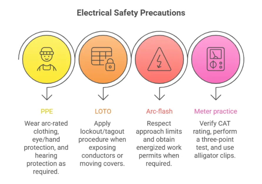
- PPE: Arc-rated clothing, eye/hand protection, and hearing protection per arc-flash study.
- LOTO: Apply lockout/tagout whenever exposing conductors or moving covers.
- Arc-flash boundaries and permits: Respect approach limits and obtain energized work permits when required.
- Meter practice: Verify CAT rating and perform a three-point test (known live -> test point -> known live). Use alligator clips and long leads for hands-free stability.
Documentation Kit
- Standardized test form or app: Capture timestamps, currents, and photos for tighter QA/QC and cleaner handoffs.
- Chain-of-evidence foldering: Store results by project -> panel -> circuit to defend scope and document decisions.
Software
- Document intelligence platform: Auto-builds a project-specific test plan from specs and one-line diagrams (for example, feeders over X ft, motor branches, long LED runs).
- Generative workflows: Build test lists, capture readings, and generate pass/fail logs with RFI drafts when
%VDexceeds limits. - Auto-tagging: Push readings into standardized logs, link panel IDs, and flag any circuit exceeding
3%or5%standards.
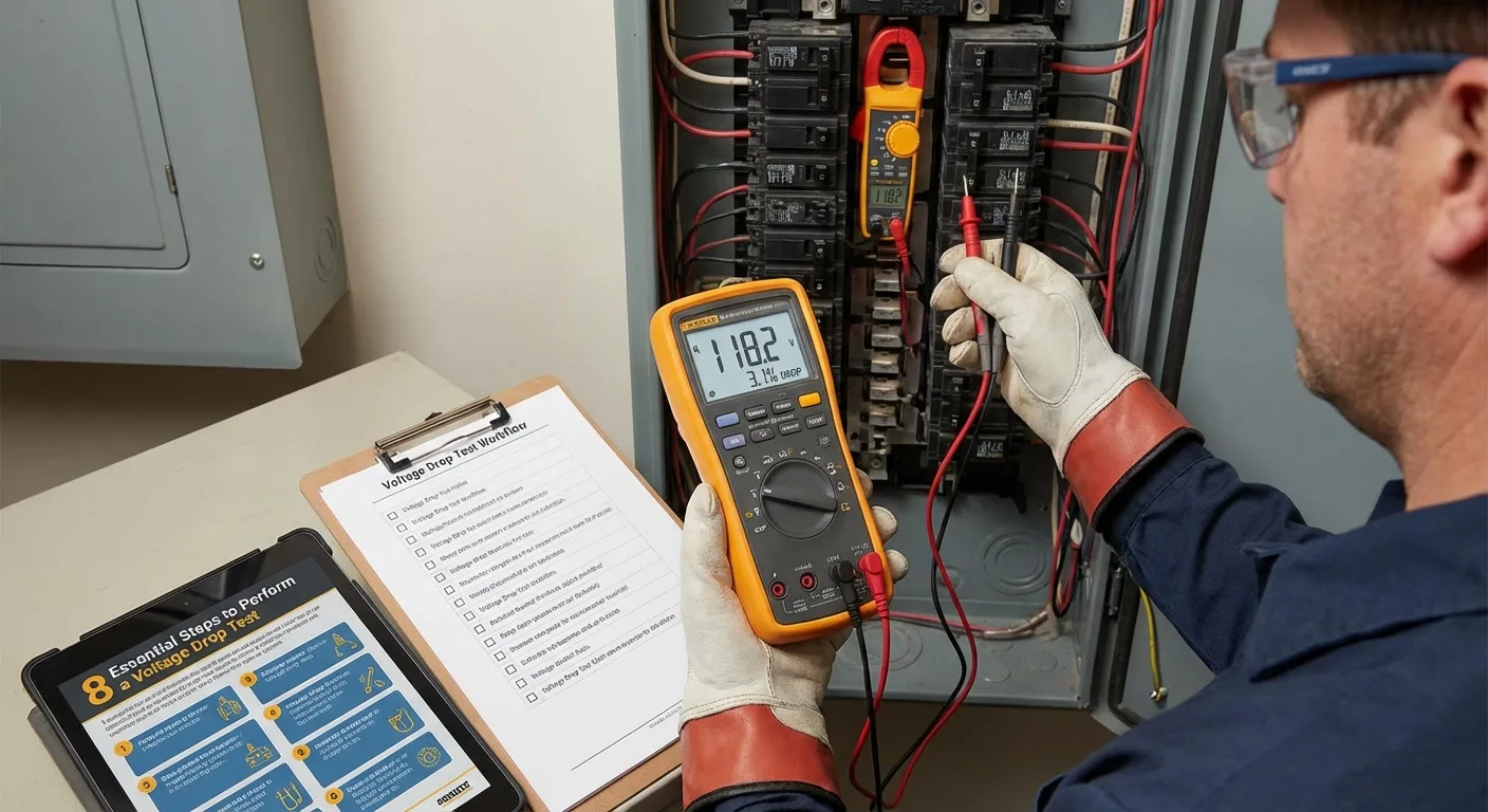
8 Essential Steps to Performing a Voltage Drop Test on a Live Circuit
Live work is extremely hazardous. It should only be done by qualified personnel following your energized work policy and permit requirements.
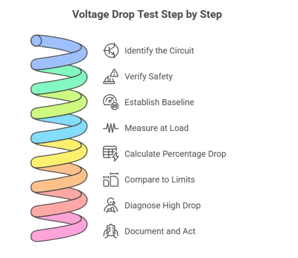
1. Identify the Circuit
Start with the paper trail: panel and breaker, circuit ID, and load nameplate. Confirm system voltage and what normal looks like (for example, running amps from submittals or a quick clamp reading). Cross-check conductor size, distance, and load data during review before final takeoff decisions.
2. Verify Safety
Suit up with required PPE and pull required permits. Confirm your meter CAT III/CAT IV rating matches the system. Perform a three-point test:
- Prove the meter on a known live source
- Take the reading
- Re-prove on the known source
3. Establish a Baseline at the Source
With the circuit under typical load (or controlled test load), place leads at accessible supply terminals (breaker lugs or equipment line side). Record Vs (source voltage), phase-to-phase or phase-to-neutral as applicable, and capture current with a clamp.
This is your panel baseline. Avoid VFD output terminals for voltage drop testing; the output waveform is non-sinusoidal and not comparable to source voltage.
4. Measure at the Load
Move to equipment terminals (motor peckerhead, VFD line input, LED driver input, or receptacle). Keep the same load condition; no-load readings can be misleading. Record Vl and note flicker, relay chatter, or VFD alarms.
5. Calculate Percentage Drop
Use:
%VD = ((Vs - Vl) / Vs) x 100
For three-phase line-to-line measurements, normalize to source line-to-line voltage. For line-to-neutral circuits, normalize to source line-to-neutral voltage.
Log actual current and capture inrush/peak so you can evaluate locked-rotor sag. Note measured phases and current at test time.
6. Compare to Limits
Check project specs, owner criteria, and manufacturer tolerances. If silent, apply your firm standard (for example, 3% branch, 2% feeder, 5% total) and document the basis.
Make a clear pass/fail call. If over limit, trigger a workflow to assemble an RFI with readings, photos, and references.
7. Diagnose if It's High
If drop is high:
- Under load: suspect long runs, undersized conductors, or series resistance from damaged/corroded terminations.
- No load: source and load should be nearly identical; large delta often means measurement error, reference mismatch, or upstream variation.
- Inspect and torque-check lugs/splices; look for oxidation, loose set screws, or heat discoloration (thermal camera helps).
- Verify conductor size/length, aluminum prep, and any shared/undersized neutrals on nonlinear loads.
- For motors, capture min/max during startup to see sag.
If still over limit, package readings/photos and issue an RFI.
8. Document and Act
Capture a close-up of meter readings and a context shot with panel/circuit labels. Log timestamp, tester, panel/circuit ID, conductor size/length, ambient temperature, source/load voltage, current, and threshold used.
If design distance or added scope drives non-compliance, package the data into an RFI/CO before it becomes a warranty dispute.
With a document intelligence platform, this loop moves faster: pull allowable %VD from specs/cut sheets, flag addenda changing run lengths or conductor sizes, generate test checklists, and auto-draft pass/fail logs plus RFIs.
Prove Performance and Protect Margins with Pelles
Voltage drop testing confirms your circuit will deliver under real load, protecting bid assumptions and reducing control-fault callbacks. Done right, you get fewer surprises and cleaner closeout.
Pelles slots into the workflow where your team already works. DoubleCheck surfaces exact spec clauses and manufacturer minimums so your pass/fail threshold is explicit. Compare keeps you aligned to latest revisions so tests and RFIs match the current set. Generative workflows capture source/load readings into clean logs and auto-draft RFIs when %VD exceeds limits.
Your organizational wiki then preserves thresholds, upsizing rules, and torque specs so the next crew starts with better context.
Book a call to see how Pelles supports trades from bid to build and automates documentation-heavy workflows.